System Curve For Pumps
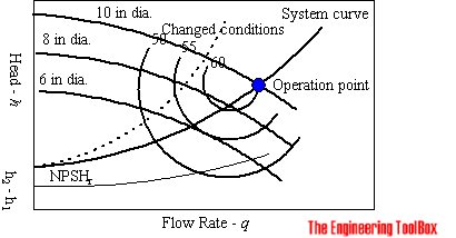
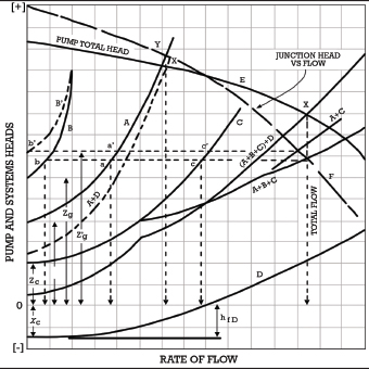
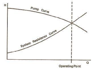
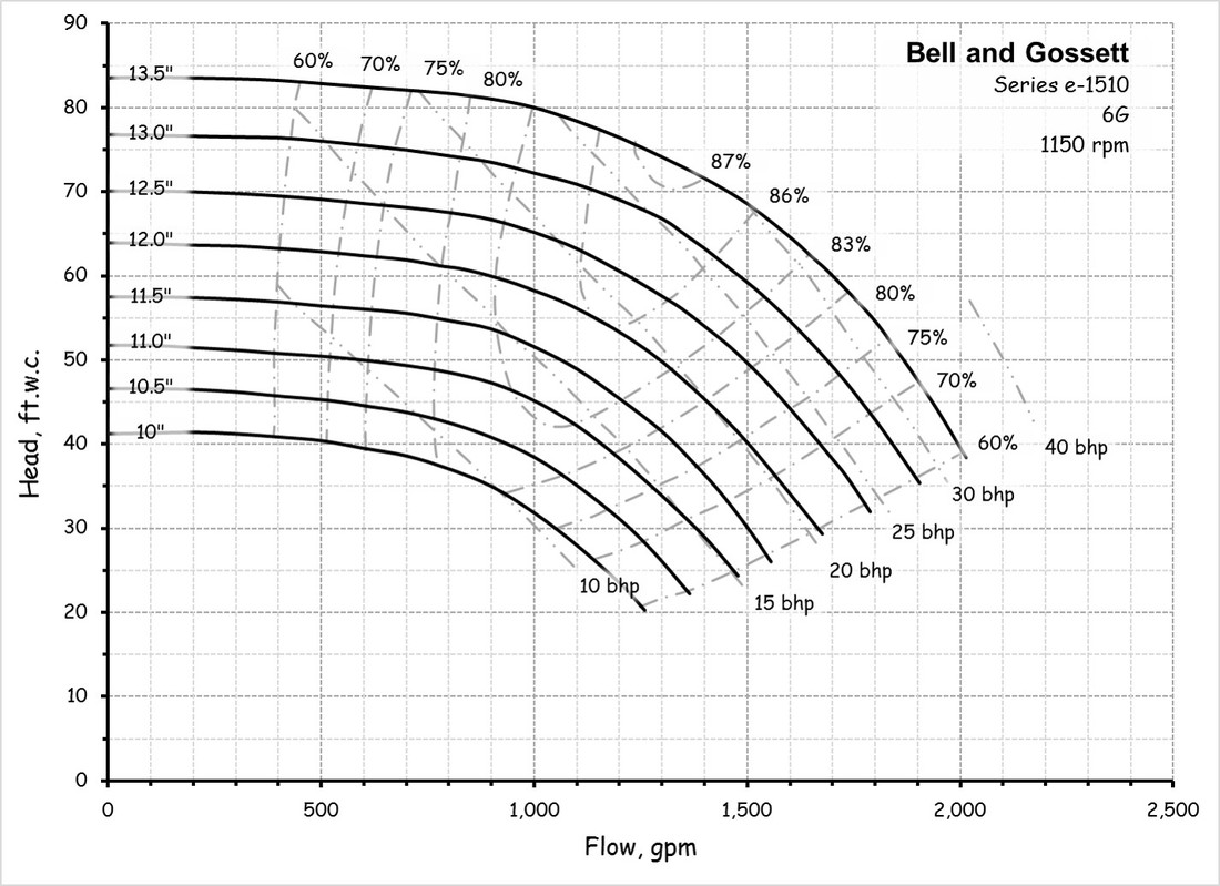
System curve for pumps. Part 1 - How to Draw a Centrifugal Pump System Curve in. By superimposing the manufacturers pump curve on a pipeline resistance curve a pump system curve or system resistance curve is identified. Pump curves are usually plotted for different impeller diameter values.
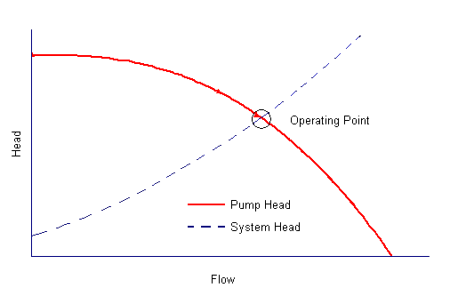
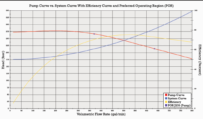
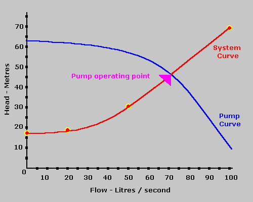
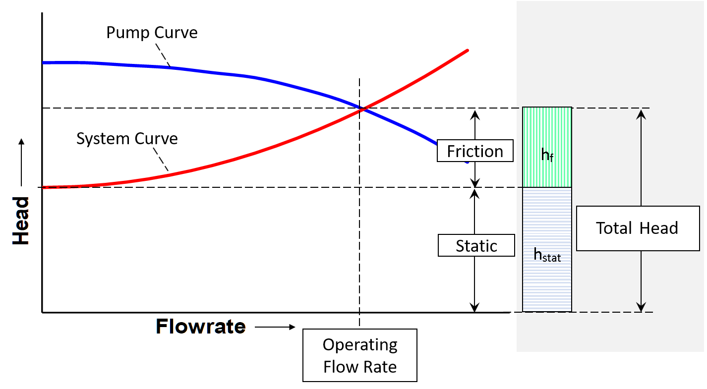
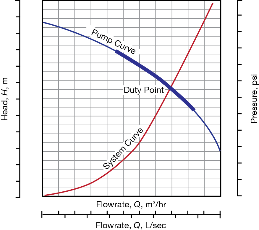
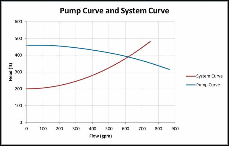
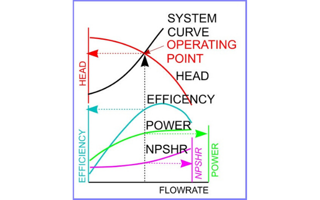
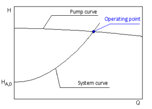
The performance of the pump its head and flow rate is shown on the manufacturers supplied pump curve. Load on the pump H sys system head Pumping effort and friction are accounted for when the system curve intersects the pumping head curve HpumpQ Plot this versus Q Obtain this versus Q from the manufacturer Where the two intersect thats where the pump operates. 4 Operating point The intersection of.
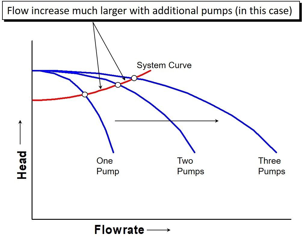
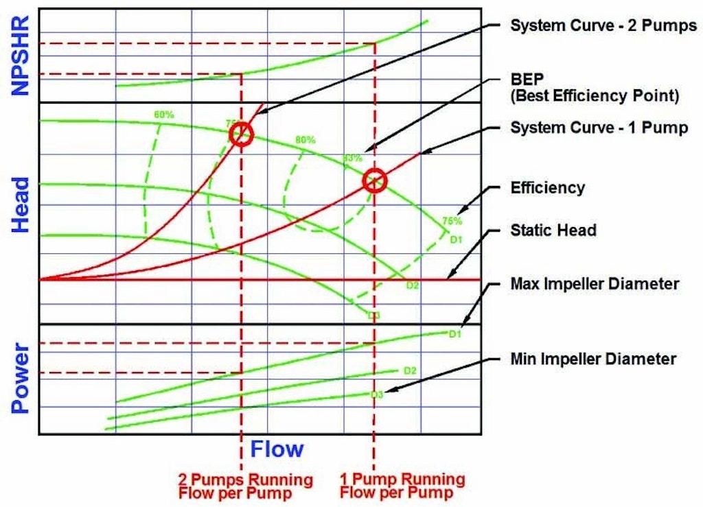
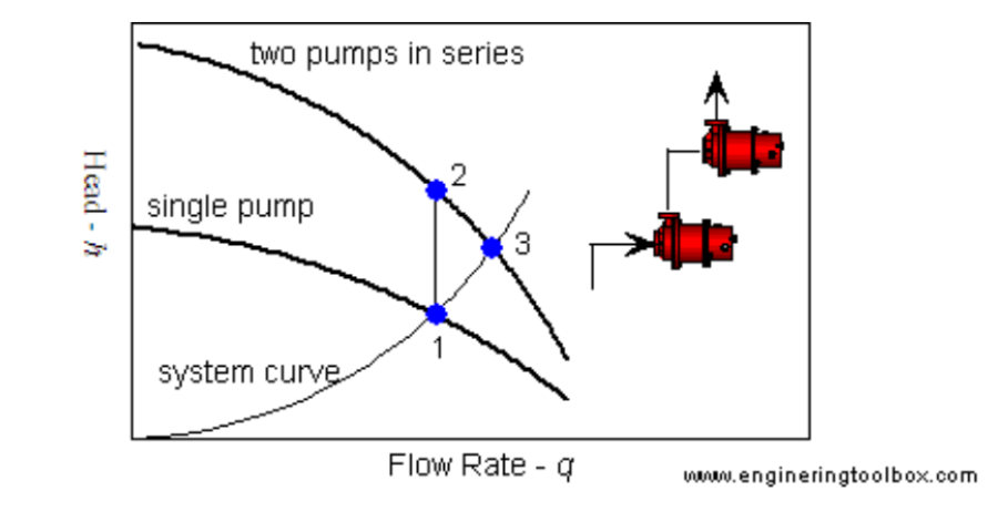
With a constant flow rate the combined head moves from 1 to 2 BUT in practice the combined head and flow rate moves along the system curve to point 3. To predict the system performance a combined curve for all pumps can be produced by adding the individual flows from each pump curve at a common head. This video covers how to develop a system curve for a simple pumping system.
Pump curves represent the energy that is put into a system. How to read a pump curve. System curves represent what the system takes out.
Point 1 is where the system operates with one pump running. The head for each pump equals. If the source reservoir is above the destination the system curve is shifted down.
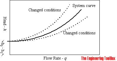
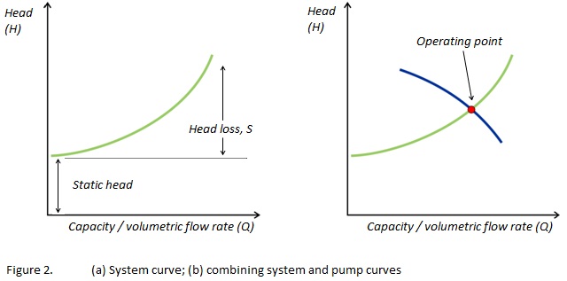
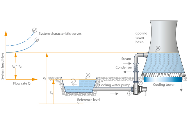
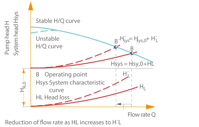
The proper pump can be selected by combining the System Curve and the Pump Curve. The system curve helps quantify the resistance in a system due to friction and elevation change over the range of flows. The system characteristic curve see Characteristic curve represents the relationship between the system head Hsys and the flow rate Q.
Best Efficiency Point - BEP. Note that for two pumps with equal performance curves running in parallel the head for each pump equals the head at point 3.
In my opinion the system curve is the single most important component of the pump selection process.
In my opinion the system curve is the single most important component of the pump selection process. Part 1 - How to Draw a Centrifugal Pump System Curve in. With a constant flow rate the combined head moves from 1 to 2 BUT in practice the combined head and flow rate moves along the system curve to point 3. The performance of the pump its head and flow rate is shown on the manufacturers supplied pump curve. Point 1 is where the system operates with one pump running. The value of the pump system curve is it shows graphically how the pump and system interact. Note that for two pumps with equal performance curves running in parallel the head for each pump equals the head at point 3. A system curve is a graphical representation of the head and flow characteristics of a hydraulic system. This is the head and flow rate for the given pumpsystem combination.
The system characteristic curve see Characteristic curve represents the relationship between the system head Hsys and the flow rate Q. System Curves raphical representation of the relationship between discharge and head loss in a system of pipes The system curve is completely independent of the pump characteristics The basic shape of the system curve is parabolic because the the head loss equation and on the velocity head term is 20 or nearly 20 The system curve will start at zero flow and zero head if there is no. The operating point is where the system curve and the actual pump curve intersects. The system characteristic curve see Characteristic curve represents the relationship between the system head Hsys and the flow rate Q. It is often parabola-shaped and does not generally pass through the origin of the HQ coordinate system. 1 System characteristic curve and Fig. The system curve is half of the requirement to selecting the right pump for you.


















Post a Comment for "System Curve For Pumps"